Serial FPDP Protocol
A Deep Dive into sFPDP Architecture

If you had worked with high-speed data acquisition, radar, or medical imaging, you have probably bumped into sFPDP (Serial Front Panel Data Port). Defined by the VITA 17.1 standard, sFPDP is designed to stream continuous, high-bandwidth data point-to-point with virtually zero overhead. But if you try to learn how the protocol actually works, you will quickly hit a wall. Because the official standard (ANSI/VITA 17.1) is kept behind a paywall, there is a massive lack of open-source tutorials explaining its architecture.
Originally, parallel FPDP transferred data at speeds up to 160 MB/s using a 32-bit synchronous ribbon cable. While designed for real-time data streaming with minimal delay, parallel FPDP was severely limited by short cable lengths (1 to 5 meters). To overcome this limitation, the protocol evolved into sFPDP (VITA 17.1). By serializing the data stream, sFPDP allows for connections up to 10 kilometers using fiber optic cables.
Today, we are going straight down to the wire to look at exactly how an sFPDP frame is constructed, how it handles sideband signaling, and how it strictly manages physical link boundaries.
The Anatomy of an sFPDP Frame
Unlike Ethernet, which carries heavy routing headers, sFPDP is built for pure streaming speed. A complete transmission is called a Frame, and it is strictly bookended by control sequences called Ordered Sets.
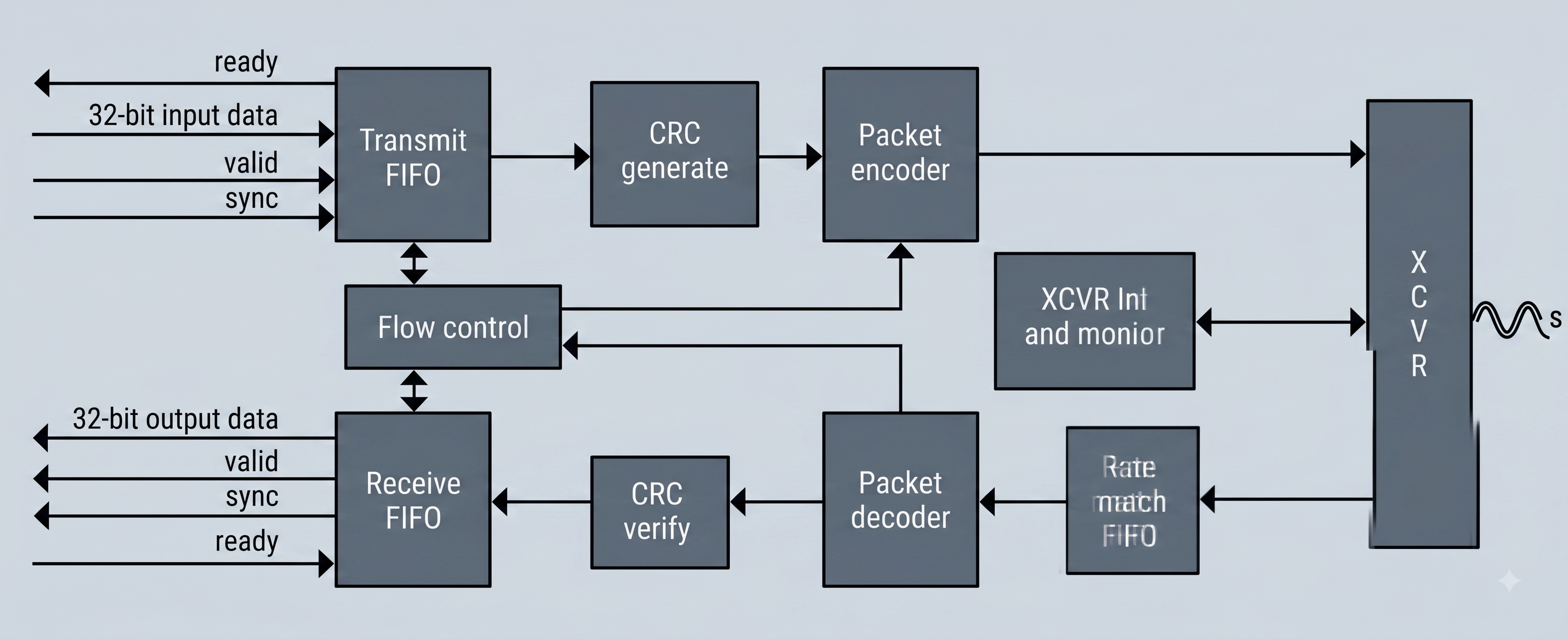
A standard frame consists of four distinct phases:
- Start of Frame (SOF)
- Data Payload
- CRC Checksum
- End of Frame (EOF)
The Start of Frame (SOF): The “Virtual Wire”
When the transmitter is ready to send data, it cannot just start blasting raw bits. It must alert the receiver by sending a 32-bit Start of Frame (SOF) Ordered Set. Every Ordered Set begins with a special 8b/10b control character—almost always K28.5 (Hex: BC). When the receiver sees K28.5, it knows the next three bytes are control instructions, not payload data.
Ordered sets are simply fixed 4-byte (32-bit) sequences used to control the physical link. They combine special K-characters (like K28.5, K27.7, etc., from 8b/10b encoding) with data bytes to tell the receiver what is happening on the line.
Virtual Sideband Signaling
One of the smartest features of sFPDP is how it handles hardware flags. If you have two boards connected by a single fiber optic cable, you don’t have extra copper wires to send hardware interrupts. sFPDP solves this by sampling user-defined pins (like Programmable I/O PIO1, PIO2, and Direction DIR) at the exact moment the frame starts, and mathematically packing their 1 or 0 status directly into the SOF ordered set.
| Input (pio1, pio2, dir) | SOF Assignment | Description | Disparity | Byte Sequence |
|---|---|---|---|---|
| 3’b000 | SOFc1 | SOF Connect Class 1 | Negative | BC B5 17 17 |
| 3’b001 | SOFi1 | SOF Initiate Class 1 | Negative | BC B5 57 57 |
| 3’b010 | SOFn1 | SOF Normal Class 1 | Negative | BC B5 37 37 |
| 3’b011 | SOFi2 | SOF Initiate Class 2 | Negative | BC B5 55 55 |
| 3’b100 | SOFn2 | SOF Normal Class 2 | Negative | BC B5 35 35 |
| 3’b101 | SOFi3 | SOF Initiate Class 3 | Negative | BC B5 56 56 |
| 3’b110 | SOFn3 | SOF Normal Class 3 | Negative | BC B5 36 36 |
| 3’b111 | SOFf | SOF Fabric | Negative | BC B5 58 58 |
While these ordered sets hold specific purposes in Fibre Channel networking (like Class of Service and Fabric routing), in sFPDP they serve a simpler function: they are used as interrupt signals or to pack different sensors into their own specific SOF ordered set to differentiate between data streams.
For example, when two sensor data streams need to be sent over the same fiber optic cable, the first sensor data can use SOFc1 and the second sensor can use SOFn1. This allows the data streams to be easily segregated on the receiver side. The receiver extracts these bits from the SOF and drives its own local pins to match, creating a seamless “virtual wire” across the link.
The ordered set details mentioned above are taken from the Fiber Channel Interface Manual, Rev D. Refer to this manual for further technical details regarding ordered sets and 8b/10b encoding.
The Data Payload (And the 512-Word Limit)
Immediately following the SOF, the framer begins streaming the actual data payload. In sFPDP, data is packaged in 32-bit words. However, a frame cannot stream endlessly. Most implementations based on the VITA 17.1 standard enforce a strict maximum payload size of 512 words (2048 bytes).
- If the system has 10,000 words to send, the framer must slice the data into multiple individual frames.
- Once the internal word counter hits 512, the hardware must forcibly cap the frame, even if the data FIFO isn’t empty yet.
- If the receiver’s buffer gets dangerously full during transmission, it can send a Stop ordered set back across the wire. The transmitter must immediately terminate the payload and close the frame to prevent data loss.
Securing the Payload (CRC)
High-speed links are susceptible to bit flips from noise or jitter. To guarantee data integrity, sFPDP appends a 32-bit Cyclic Redundancy Check (CRC) to the end of the payload. The framer calculates this checksum continuously as the payload streams out. Once the payload finishes, the 32-bit CRC word is transmitted right before the EOF.
The End of Frame (EOF)
Once the CRC is sent, the framer must cap the transmission using an End of Frame (EOF) Ordered Set. A transmission doesn’t always finish perfectly. Sometimes a hardware buffer overflows, the link is interrupted, or the system just needs to send a timing signal without any actual data. Instead of sending a completely separate message to explain what happened, the transmitter just uses a specific type of EOF to give the receiver a status update on how the frame ended.
Here are the main types used in the protocol and what they mean:
- Normal EOF (EOFn): The “Standard data frame.” This tells the receiver, “The frame finished perfectly, all the data is here, process it normally.”
- Abort EOF (EOFa): The “Panic Button.” If the transmitter’s hardware fails, a FIFO buffer overflows, or it is forced to stop mid-transmission, it caps the frame with an Abort EOF. This explicitly tells the receiver, “Something went wrong on my end. Throw this entire frame in the trash.”
- Terminate EOF (EOFt / EOFdt): The “Sign Off.” These are used to tell the receiver that not only is the current frame over, but the entire sequence or logical connection is finished.
- Marker / Invalid EOFs (EOFni / EOFdti): The “Timing Syncs.” In sFPDP, these are often used for synchronization. If the hardware needs to send a “sync pulse” to the other board but has no actual payload data to send, it will create a tiny, empty frame capped with one of these markers just to pass the timing signal across the wire.
While these EOF meanings hold specific networking purposes in Fibre Channel, in sFPDP, they are cleverly repurposed to transmit hardware status information about the transmitting device. For example, EOFt, EOFdt, EOFa, and EOFn can be used as a 2-bit status map to instantly communicate hardware signals—such as a TX FIFO overflow or the transmitter’s ‘ready’ status—back to the receiver.
Running Disparity: Balancing the Wire
When transmitting high-speed data over long cables, the electrical signal must stay perfectly balanced. This means that over time, the number of 1s (high voltage) and 0s (low voltage) traveling across the wire must be exactly equal. If you send too many 1s in a row, the baseline voltage drifts upward, which can cause the receiver to read the data incorrectly. To prevent this, the physical hardware uses a trick called 8b/10b encoding. The encoder keeps a running tally of the 1s and 0s it has sent so far. This ongoing tally is called the Running Disparity (RD).
At any given moment, the Running Disparity is either:
- RD Positive (RD+): The wire currently has a surplus of
1s. - RD Negative (RD-): The wire currently has a surplus of
0s.
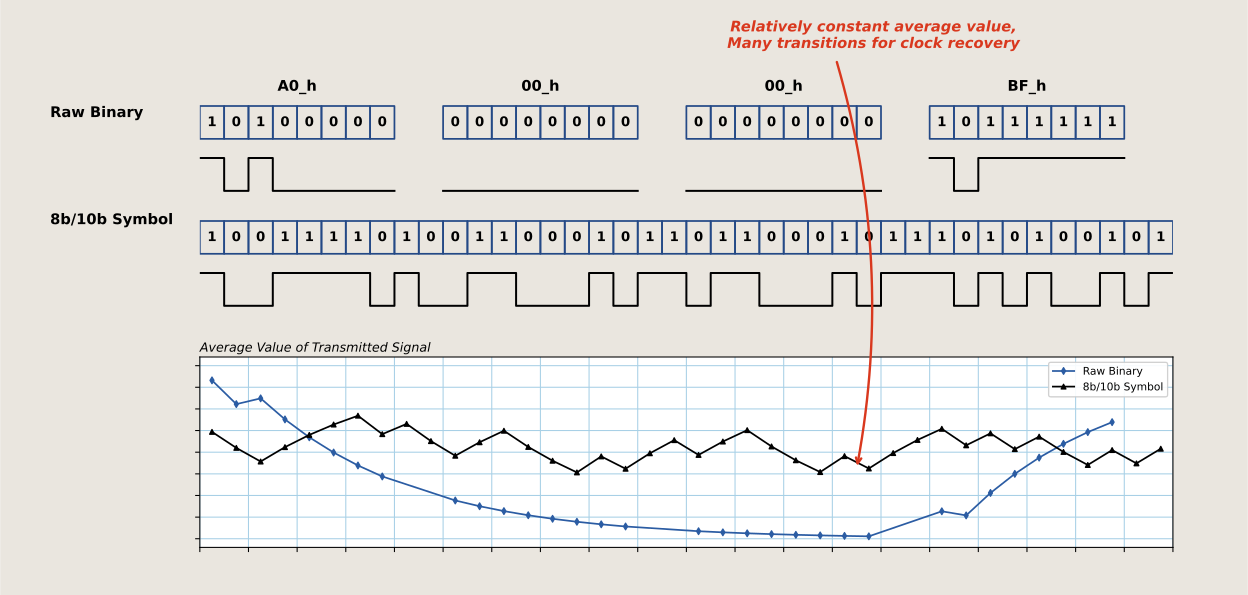
To keep the tally balanced, every standard 8-bit byte actually has two different 10-bit versions it can be translated into. One version has extra 1s another version has extra 0s. Before the transmitter sends a character, it looks at the current Running Disparity. If the wire has too many 0s (RD-), it intentionally picks the 10-bit version with extra 1s to balance the scale. For example look at the most used K28.5 control character (Hex BC) that is used to start our Ordered Sets. Depending on the wire’s current tally, the hardware will physically flip the bit pattern it sends:
| Character | Current Wire Tally | 10-bit Pattern Sent on Wire | New Wire Tally |
|---|---|---|---|
| K28.5 | Negative (RD-) | 001111 1010 (contains extra 1s) | Positive (RD+) |
| K28.5 | Positive (RD+) | 110000 0101 (contains extra 0s) | Negative (RD-) |
By constantly tracking the score and choosing the correct pattern, the framer forces the voltage on the wire to perfectly zig-zag around zero, keeping the signal healthy and stable.
The sFPDP Complete Series
What we covered today is just the high-level architecture. In the upcoming chapters, we will be looking at the actual implementation, breaking down the hardware logic module by module. Follow along below: